History of Science and Technology in Islam
ENGINEERING in Arabic-Islamic Civilization[1]
DONALD R. HILL and AHMAD Y. al-HASSAN
Part One
INTRODUCTION
The
history of
engineering in Islam is a very wide subject indeed, and it is not easy
to do it justice in a single article.
The intention
is to present
the reader
with a fair and accurate picture of the scope and significance of Muslim
achievements in this field, and to indicate how Muslim engineers served
the needs of society and how, in a number of instances, their work was
of importance in the development of modern engineering. To realize this
intention in the space available some omissions are inevitable. In the
first place, and without entering into a lengthy discussion about the
precise meaning of the term, ‘engineering’ is taken here as a concept
that involves some degree of complexity. In civil engineering, small
structures such as dwelling houses and short-span bridges have in
general been disregarded. In the mechanical field military machines are
not discussed and devices that require the frequent and repeated use of
the human hand have been omitted. There is therefore no direct
discussion of hand tools, personal weapons or textile machinery. An
exception is made in the case of instruments – surveying and
astronomical – because of the mathematical skills required for their
construction and use.
In many cases the places and dates of origin of machines or techniques
have not been established with any certainty. It is not proposed to
devote much space to an examination of the evidence for the origin of
any particular invention, particularly if it is known that it occurred
before the advent of Islam in the first/seventh century. The estimated
time and location of origin will be given, with an indication of the
conjectural element in this estimate and the possible alternatives, if
any. It should be noted that most pre-Islamic inventions were made in
the Near East that witnessed the passage of several ruling empires from
ancient times till the advent of Islam.
Medieval Islam was a prosperous and dynamic civilization, and much of
its prosperity was due to an engineering technology that assisted in
increasing the production of raw materials and finished products. In
addition, the demand for scientific instruments, and the need to cater
for the amusements and aesthetic pleasures of the leisured classes, was
reflected in a tradition of fine technology based upon delicate
mechanisms and sensitive control mechanisms. In this paper, the
contribution of engineering to Islamic civilization will usually be
demonstrated by specific examples, since space does not allow for a
detailed survey of the interactions between technology and society.
Similarly, the Islamic contribution to the development of modern
engineering will be indicated by means of citing individual cases of
technology transfer.
CIVIL ENGINEERING
Irrigation and water
supply
For the sake of convenience it is necessary to divide the subject of
civil engineering in the Muslim world into several sections, but in fact
much of the subject is broadly contained within the field of irrigation
and water supply. Dams are used to impound and divert irrigation water,
bridges to cross canals and surveying techniques to align and level
canals and qanats. Water-raising machines, which are discussed
under mechanical engineering, are of course an integral part of
hydraulic engineering schemes. In this section, therefore, we shall
confine our attention to the principal irrigation systems, and to the
means for transporting water to the fields and to urban communities.
There are four different types of irrigation. Basin irrigation,
which was the method used in Egypt from ancient times until quite
recently, consists of levelling large plots of land adjacent to a river
or a canal, each plot being surrounded by dykes. When the water in the
river reaches a certain level the dykes are breached, allowing the water
to inundate the plots. It remains there until the fertile sediment
settles, whereupon the surplus is drained back into the watercourse.
Perennial irrigation is a method of watering crops regularly
throughout the growing season by leading the water into small channels
which form a matrix over the field. Water from the main artery – a
river, major canal or qanat – is diverted into supply canals,
then into smaller irrigation canals, and so on to the fields. Terrace
irrigation is a method used in hilly country and consists of the
formation of a series of terraces stepped down a hillside. Irrigation is
by means of stored rainfall, wells, springs and occasionally qanats.
Wadi irrigation depends upon sporadic rainstorms in otherwise arid
lands. It consists of impounding the storm water behind dams and using
this water to irrigate the fields adjacent to the watercourses. The
famous dam at Ma’rib in the Yemen was the focal point of such a system.
Following its original construction in the eighth century B.C.E. it was
successively raised, not to impound water for long periods but to raise
the wadi floods to increasingly higher levels in order to irrigate more
and more land by means of a canal system which used the wadi itself as a
drain. The final breakdown of the dam is thought to have occurred about
a quarter-century before Muhammad’s birth. From the second century
B.C.E. until the beginning of the first century C.E. the Nabateans in
southern Palestine and Jordan developed a thriving agriculture based
upon wadi irrigation. Whereas irrigation in the Yemen depended upon a
single large dam, the Nabateans built thousands of little barriers sited
across one wadi after another in order to divert or capture the one or
two weeks of runoff occurring each year.
All these methods of irrigation originated in antiquity and it cannot be
said that any radically new techniques have been added to the repertoire
of Egyptian and Mesopotamian engineers. It could scarcely be otherwise:
the basic problem of impounding the water, conducting it to the fields
and finally draining the surplus remains as it has always been.
Irrigation, and particularly perennial irrigation, however, is a branch
of civil engineering which has always demanded a high degree of
technical and administrative skills. The construction of dams, canals
and qanats, matters to do with water flow and control, and
elaborate surveying problems; all present themselves uncompromisingly
and demand the attention of experts. From one area to another, there
will always be differences in hydraulic conditions, climate, soil and
terrain, so that the engineers must apply their knowledge and experience
to produce the best system for a given set of conditions.
It is sometimes said that large cities are one of the main
characteristics of Islamic civilization, and it is of course true that
great cities such as Baghdad, Cairo and Cordoba, with their flourishing
economic, commercial and intellectual life, were a major component of
that civilization. It hardly needs emphasizing, however, that life in
these large urban centres would have been impossible without the support
of a thriving agriculture. Many Muslim cities were founded after the
advent of Islam – e.g. Baghdad, Basra and Shiraz –- and we therefore
find that the efforts of the engineers were taxed to the utmost either
in extending existing systems or in creating completely new ones.
From the
start of the Islamic Caliphate Irrigation works and water distribution
were prominent among the State’s achievements. When al-Basra was
established during Umar’s period, he started simultaneously building
some canals for conveying water and for irrigation. Two important canals
were built linking al-Basra with the Tigris River. These were al-Ubulla
River and the Ma`qil River. Basra obtained the necessary drinking water,
and the two canals were the basis for the agricultural development for
the whole Basra region.[2]
‘Umar also devised the policy of cultivating barren lands by assigning
such lands to those who undertook to cultivate them. This policy, which
continued during the Umayyad
period also, resulted in the
cultivation of large areas of barren lands through the construction of
irrigation canals by the State and by individuals.
The various governors who were appointed by the Umayyads constructed
several works to prevent the formation of new swamps and to dry old
ones, through the building of dams that regulated the flow of water. We
find in the original Arabic sources details about the irrigation works
which were constructed in Iraq and in Syria in the regions of al-Basra,
al-Kufa, Wasit, al-Bata’ih, al-Raqqa and several other areas.[3]
When the Abbasids assumed power in the second/eighth century they
followed the same policy. They expanded greatly the existing irrigation
system, mainly to cater for the needs of the new city of Baghdad, whose
population at its zenith was about 1 500 000. The network of canals
between the Euphrates and the Tigris was extended, the great Nahrawan
canal to the east of the Tigris was lengthened and two new systems on
the rivers ‘Uzaim and Diyala were added.
[4]
Although
there was some irrigation in Spain in Roman and Visigothic times, the
large systems along the River Quadalquivir and in the province of
Valencia were Muslim achievements. The rulers of al-Andalus and many of
their followers were of Syrian origin, and the climate, terrain and
hydraulic conditions in parts of southern Spain resemble those of Syria.
It is hardly surprising, therefore, that the irrigation methods –
technical and administrative – in Valencia, for example, closely
resemble the methods applied in the Ghuta of Damascus.
[5]
There were
many other irrigation systems in the Muslim world, ranging from the
great canal networks of Egypt and Iraq, down to village fields watered
from one or two wells. One of the largest systems was centred on the
city of Marw in Khurasan on the River Murghab, which provided the
irrigation water for extensive farmlands. In the fourth/tenth century
the superintendent of irrigation at Marw was said to have had more power
than the prefect of the city, and to have supervised a workforce of 10
000 men. Greatly surpassing this, however, was the land of Sughd (Bilad
al-Sughd ) – now part of
Uzbekistan.
The mainstay of its fertility was the Sughd River, now called the
Zarafshan, which flowed through the great cities of Samarkand and
Bukhara. At the height of its prosperity in the third/ninth and
fourth/tenth centuries this land was rich and fertile beyond compare,
its agriculture supported by a vast network of canals extending for many
miles around the two cities.[6]
Given the large numbers of men required to construct, maintain and
control the large irrigation systems, it is hardly surprising that most
of the enterprises were under State control, although it was not unusual
for work to be let out to subcontractors.[7]
There are several Arabic treatises which tell us a good deal about the
methods used for surveying and some of them discuss the excavation of
new canals and methods for maintaining existing ones. We shall discuss
land surveying in a separate section, but a section on quantity
surveying in a treatise written in Iraq in the fifth/eleventh century is
worth mentioning, since it also provides us with information about
irrigation works in general.[8]
Instructions are given for calculating the quantities of earth to be
excavated from canals of given lengths, widths and depths and for
converting these quantities into manpower requirements. The canal banks
were reinforced with bundles of reeds, and the man-hours required for
preparing and placing the bundles are given. For excavation, the number
of diggers (called ‘spades’) was first calculated, and to these were
added the numbers of carriers to each spade, which depended on the
distance the spoil had to be carried. Overheads for ancillary workers
and supervision were then added. There was a set price for each task, so
in the end a Bill of Quantities was produced which would provide the
estimate for the cost of the works and serve as a guide for the
recruitment of labour. Or, if the project was let out to subcontract,
the Bill of Quantities would be the main document for awarding the
contract and for the subsequent measurements and payments. Quantity
surveying methods have not therefore changed materially over the
centuries. From this treatise, and elsewhere, we get a picture of a
highly organized State enterprise, with an army of bureaucrats,
engineers and surveyors, controlling a very large labour force, whose
productivity and rates of pay were closely specified.
It is not usually easy to separate irrigation from water supply because
both systems were derived from the same hydraulic works. Thus a dam
would provide for both the town supply and the needs of the farmers,
with one main feeder channel going to the irrigation system and another
into the town. Or a canal would be led out from the main feeder canal
into the urban centre. It was collected in a reservoir inside, or just
outside, the city walls, and was conducted from there through pipes or
open channels to the baths, fountains, houses for ritual ablutions,
private and public buildings, and gardens. A particularly impressive
example of artificial storage reservoirs can still be seen just outside
the city of Qayrawan. Two large linked cisterns for receiving the waters
of the Wadi Merj al-Lil when it was in flood were completed in the year
248/862-3. Although they appear to be circular, both are actually
polygonal, the larger having a diameter of just under 130 m, the smaller
one a diameter of 37.4 m. The smaller receives the waters of the wadi
and acts as a settling tank; a circular duct several metres above its
base connects it to the larger cistern, which has a depth of about 8 m.
On leaving the larger cistern, the water is decanted a second time into
two oblong covered cisterns.[9]
One of the most
effective methods for providing water in regions without perennial
streams is the qanat, an almost horizontal underground
conduit that conducts water from an aquifer to the place where it is
needed. The technique probably originated in northern Iran in the eighth
century B.C.E. It was in widespread use in the Muslim world in the
medieval period and up to modern times. Indeed, recent estimates have
shown that 75 per cent of all water used in Iran at the present time
comes from qanats and that their total length exceeds 100 000
miles. The city of Teheran alone has thirty-six qanats,
all originating in the foothills of the Alburz 8 to 16 miles away, with
a measured flow of 6.6 million gallons a day in spring and never below
3.3 million in the autumn.[10]
Outside Iran, qanats are still in use in parts of the Arab world,
notably in the south-east of the Arabian Peninsula and in North Africa.
The qanat system was used by the Umayyad and the Abbasid caliphs.
The Caliph Al-Mutawakkil (847-866) constructed a qanat system for the
supply of water to his new palace at Samarra. Recent excavations there
showed that the water was obtained from ground water of the upper Tigris
and conveyed to Samarra in qanat
conduits totaling 300 miles in length.[11]
Al-Karaji’s Inbat al-miyah al-khafiyya (The Bringing Out of Hidden
Waters) is a technical treatise written about 1000 C.E. which
gives good details on the finding of the water level, instruments for
surveying, construction of the conduits, their lining, protection
against decay, and their cleaning and maintenance
[12]
The construction of qanats is in the hands of experts (muqanni)
and the secrets of the profession are largely handed down by word of
mouth from father to son. The termination of the qanat,
either farmland to be irrigated or a community to be provided with
potable water, or both, will be known in advance, as will the general
location of likely aquifers. One of the main skills of the muqanni
lies in determining, by examining the alluvial fans for traces of
seepage and hardly noticeable changes in vegetation, precisely where the
trial well is to be dug. When the excavators reach the impermeable layer
the well is left for a few days while the muqanni estimates the
potential yield of the well by hoisting up measured quantities of water
and at the same time observing any fall in the water level. If
necessary, further wells are sunk to ensure that genuine groundwater has
been reached; the shaft with the highest yield is chosen as the ‘mother
well’. The next step is for the surveyor – or senior muqanni –
to determine the route, gradient and precise outlet of the qanat.
The route will be selected according to considerations of terrain
and, in some cases, questions of ownership. To start the survey, a long
rope is let down into the mother well until it touches the surface of
the water, and a mark is made on it at ground level. The surveyor then
selects a spot on the route 30 to 50 yards from the mother well for the
first ventilation shaft. A staff is held on this spot by a labourer, and
the surveyor measures the fall with a level. Nowadays a modern surveying
level may be used but in earlier times one of the instruments described
in the section below on surveying was used. A second mark is made on the
rope coinciding with the measurement on the staff; the distance from
this mark to the lower end of the rope will be the depth of the first
ventilation shaft. He continues to level in this way along the route,
marking the rope at the location of each shaft, until he reaches the end
of the rope. He has then reached a point on the ground at the same level
as the surface of the water in the mother well. For the mouth of the
qanat he now chooses a place below this level, but higher than the
fields, and divides the drop from the level point to the mouth by the
number of proposed ventilation shafts and adds this amount to the
previously surveyed depth of each shaft. In this way be determines the
gradient of the conduit, which is usually from 1 : 1000 to 1 : 500.
After completion of the survey, a number of guide shafts, about 300
yards apart, are driven under the supervision of the surveyor. Then the
rope with the marked length of each vertical shaft is handed to the
muqanni, who now begins to work with his assistants by
driving the conduit into the alluvial fan, starting at the mouth. At
first the conduit is an open channel, but it soon becomes a tunnel.
Another team sinks ventilation shafts ahead of the tunnellers, and
labourers haul the soil up to the surface through these shafts. Two oil
lamps are kept burning on the floor of the conduit; sighting along
these, the muqanni keeps the tunnel in alignment, and they also
serve as a warning of poor air, since they go out before there is a
danger of a man suffocating. As the work nears the mother well great
care has to be taken in case the muqanni misjudges the distance
and strikes the full well, in which event he might be swept away by the
sudden flow. It can be seen, therefore, that the construction of
qanats is a special example of the difficult and dangerous
profession of mining (see Figure 1). It may be considered as one of the
most successful of man’s inventions, since it has been in continuous use
for over 2500 years.[13]
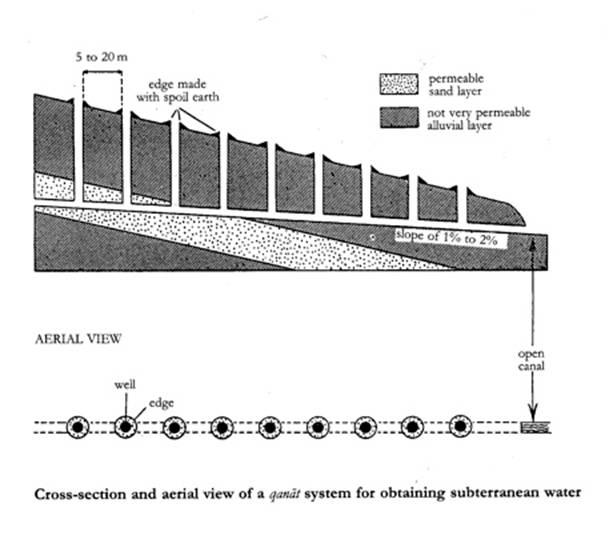
Fig. 1 –
The qanat
Dams
Dams are required in most hydraulic systems, whatever their purpose, but
the functions of dams vary. In wadi irrigation, as we have seen, they
are used to trap the floodwaters that result from heavy but infrequent
downpours, so that the water-level is raised above that of the
surrounding fields, to which it can then be conducted under gravity. For
perennial irrigation dams are used to divert water from streams or
rivers into the canal network. The impounding of rivers behind dams
gives more control over the supply throughout the year. As with wadi
irrigation, it also allows the water in the reservoir to be gravity-fed
into irrigation and town supply systems. A further advantage, if the
water is to be used for hydro-power, is that there is a high, fairly
constant head of water, which would not be the case if the river were
unregulated.
There are two basic types of dam – gravity and arch. The first, as its
name implies, relies upon the weight of the dam to withstand the
pressure of the water. For additional strength, buttresses are sometimes
added to the downstream wall. As with all hydraulic structures, good
foundations are of the utmost importance, since failure can occur if the
scouring action of the water undermines the foundations. Arch dams are
designed to resist the force of the water and silt by horizontal arch
action and are adaptable only to those sites where the length is small
in comparison to the height and the sides of the valley are composed of
good rock to resist the arch thrust at the haunches. With very rare
exceptions true arch dams were not built before modern times.
The selection of the materials of construction was influenced partly by
the design of the dam and partly by availability. Earth dams were common
and are still in widespread use today. They are perfectly satisfactory
for certain kinds of service, provided they have a core of clay or other
impermeable material and plenty of overflow capacity, but they are not
really suitable for high dams. In certain areas, notably lower Iraq,
earth dams were almost universal; they were (and are) quite adequate for
diverting rivers into canal systems and, in any case, the cost of
transporting large quantities of stone would have been prohibitive. In
other areas, where higher dams were needed, some form of masonry
construction was necessary. This could be of dressed stone, mortared or
not, random rubble or concrete. Quite frequently, dams were constructed
by building two masonry walls with a gap between them, and then filling
the gap with cheaper material such as earth or rubble. If the dam was
designed to discharge overflow water from its crest, this had to be of
stone or concrete, since earth would quickly have been worn away by the
action of the water.
Roman and Sasanid dams were carefully maintained, but the demands for
irrigation water and power was so great that in the more populous
provinces dams became more numerous than they had been in pre-Islamic
times. Many new dams were necessary as part of the extensions to the
hydraulic systems in Iraq.
Perhaps the most impressive of these dams, the remains of which can
still be seen, was a diversion dam over the River ‘Uzaym at the point
where it leaves the hills called the Jabal Harmin. The main body of the
dam is a masonry wall 575 feet long which at the western end turns
through a right angle and continues for 180 feet to form one bank of the
canal called Nahr al-Batt. The dam has a maximum height of something
over 50 feet, but this rapidly reduces towards the sides. In fact for
the first 150 feet at the eastern end, the dam is only 13 feet high. The
cross-section of its central portion has a neat trapezoidal profile, 10
feet thick at the crest and 50 feet thick at the base. The water face is
vertical and the air face is built to a uniform slope with the masonry
stepped. The dam was built of cut masonry blocks throughout, connected
with lead dowels poured into grooves. This is quite a common Muslim
technique and in the ‘Uzaym dam was apparently used as a complete
alternative to mortared joints. The alignment of the structure is not
straight, and this reflects an attempt, as usual, to utilize the natural
shape of the site as advantageously as possible.[14]
In Iran the Muslims added dams to the existing Sasanid systems. A new
dam called the Pul-i Bulaiti was built at Shustar on the River Karun,
the main purpose of which was to provide power for milling. The mills
were installed in tunnels cut through the rock at each side of the
channel, with the dam providing the necessary head of water. Another
example is the bridge-dam at Dizful which was used to power a great
water-wheel working a mechanism which raised water 50 cubits and
supplied all the houses of the town.
[15]
The Buwayhids held the real power in Iraq and Iran from 320/932 until
454/1062, and the greatest builder of the dynasty was ‘Adud al-Dawla.
Among his works was the impressive dam called the Band-i Amir, built
about 349/960 over the River Kurr in the province of Fars between Shiraz
and Istakhr. This dam was seen by the geographer al-Muqaddasi shortly
after it was constructed. He speaks of it as follows:
‘Adud al-Dawla closed the river between Shiraz and Istakhr by a great
wall, strengthened with lead. And the water behind it rose and formed a
lake. Upon it on the two sides were ten water-wheels, like those we
mentioned in Khuzistan, and below each wheel was a mill, and it is today
one of the wonders of Fars. Then he built a city. The water flowed
through channels and irrigated 300 villages.[16]
This dam, which is some 30 feet high and 250 feet long still survives.
It is made of solid masonry and does make use of a rubble masonry core.
Iron bars set in lead were used to connect the blocks. Both Al-Muqaddasi
and Ibn al-Balkhi agree that the stones were set in mortar, and this, in
addition to binding the whole construction together, would also have
served to make the dam watertight. The use of “tempered cement and
sifted sand” indicates that the engineers were aware of the need for
careful preparation of their mortar. Al-Balkhi writes ”even an iron tool
could not scratch it” This indicates that the mortar was of excellent
quality and that the dam was a very thorough and solid piece of work. It
is not at all surprising that it has had such a long and useful life.[17]
There are many Muslim dams in Spain, a large number of which were built during the fourth/tenth century, the golden age of Umayyad power in the peninsula. In this period, for example, many small dams, or azuds, were built on the 150-mile-long River Turia, which flows into the Mediterranean at Valencia. (In passing it is important to note the Spanish word azud, from Arabic al-sadd, one of very many modern irrigation terms taken directly from Arabic and certain proof of Muslim influence on Spanish technology.) Eight of these dams are spread over six miles of river in Valencia, and serve the local irrigation system. Some of the canals carry water much further, particularly to the Valencian rice fields. These, of course, were established by the Muslims, and continue to be one of the most important rice-producing centres in Europe. All eight dams are similar in construction, being fairly low with vertical water faces and stepped air faces. The cores consist of rubble masonry and mortar, and the structures are faced with large masonry blocks with mortared joints. Sluices in the outflow canals permitted surplus water to drain back into the river during normal operation, and occasionally they would be opened to their full extent in order to de - silt the approaches to the canal mouth. Such scouring sluices are absolutely essential to prevent the silt which collects behind a dam from choking the canal intakes and the canals themselves (see Figure 2). The foundations of these dams are massive; the masonry of the structure extends some 15 feet into the river bed and is supported on rows of wooden piles. These relatively massive foundations for low dams are accounted for by the fact that there are occasional dangerous floods in which the flow of the Turia is increased a hundredfold. The dams are then submerged to a depth of nearly 20 feet and must resist the battering of water, stones, rocks and trees. Because they are so low and flat and are provided with deep and very firm foundations, the Turia dams have been able to survive these conditions for 1000 years.[18]
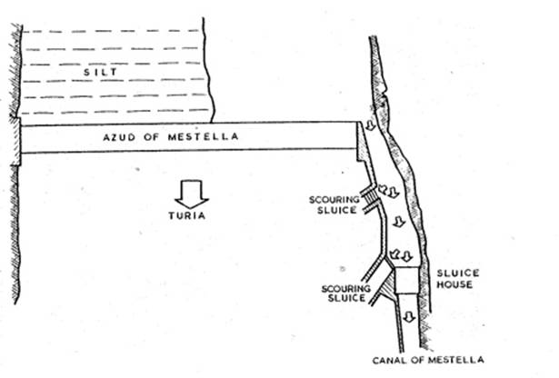
Fig 2 –
Mestella dam: desilting sluices
Not the least of the problems facing the builders of dams is that the
energy of the water spilling over the crest of a dam can, over the
years, undermine the foundations on the downstream side. A satisfactory
solution to this problem is demonstrated by a Muslim dam near Murcia on
the River Segura. The air face of the dam had a large surface area, and
this was put to good use. Water flowing over the crest initially fell
vertically through a height of 13-17 feet on to a level platform, 26
feet wide, running the length of the dam. This served to dissipate the
energy of the water spilling over the crest. The overflow then ran to
the foot of the dam over flat or gently sloping sections of the face. In
this way the whole dam acted as a spillway and the energy gained by the
water in falling 25 feet was thereby dissipated, so greatly reducing the
risk of undermining the downstream foundations. From this example – and
many others could be cited – it is evident that the Muslims had a good
empirical understanding of hydraulics.[19]
Bridges
Suspension bridges with cables made of woven bamboo strips were used in
China no later than the first century B.C.E. but there is no record, of
its use in western Islam or Europe before the Renaissance. This does not
mean that they were not used and indeed it would be strange if this
simple and effective method of crossing ravines was unknown in the
Zagros, the Taurus and the mountainous regions of Spain and North
Africa. Similarly, we have no firm evidence for the use of cantilever
bridges in Islam, apart from Afghanistan, where they had been built
from, at the latest, the fifth century C.E. onwards. These are also an
excellent method of crossing ravines in hilly country, but being made of
timber they do not have a long life nor do they leave traces,
particularly since in many cases modern bridges may have been built at
their sites. Usually a timber substructure is built into a masonry
abutment on either bank, and the longitudinal and transverse beams to
carry the roadway extend from the top of this supporting structure. At
the centre the two cantilever spans support a short beam section (see
Figure 3). Large modern steel bridges, such as the Forth railway bridge
in Scotland, are built on exactly the same principle. In the
fourth/tenth century a bridge over the River Tab in Iran was described
briefly by Ibn Hawqal. He says that the river was crossed by a wooden
bridge “suspended between the sky and the water, its height above the
water about 10 cubits”. He may, of course, have seen a suspension
bridge, but the cantilever type seems more likely, especially since he
makes no mention of ropes.
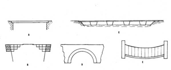
Fig. 3
–Types of bridges
There are frequent references to pontoon bridges in the works of Arabic
writers. They were very common in Iraq for crossing the two rivers and
the major irrigation canals. In the fourth/tenth century there were two
pontoon bridges over the Tigris at Baghdad, but only one was in use; the
other, having fallen into disrepair, was closed, because few people used
it. Ibn Jubayr, writing towards the close of the sixth/twelfth century,
described a bridge of large boats over the Euphrates at Hilla. It had
chains on either side “like twisted rods” which were secured to wooden
anchorages on the banks. He also mentions a similar, but larger, bridge
over a canal near Baghdad. There were also pontoon bridges on the rivers
of Khuzistan, the Iranian province adjoining Iraq, and on the Helmand
river in Sijistan (now western Afghanistan). There seems to have been a
pontoon bridge at Fustat (now Old Cairo) in Egypt for many years. In the
early part of the fourth/tenth century, al-Istakhri says that one bridge
crossed from the city to the island and a second bridge from the island
to the far bank of the river. About two centuries later, al-Idrisi
describes the same arrangement, adding that there were thirty boats in
the first bridge and sixty in the second.
Before the introduction of modern materials the masonry arch provided
the best solution for the spanning of watercourses and other obstacles.
Although they are relatively expensive to build, well-constructed arch
bridges can last for centuries and they do not interfere with river
traffic to the same extent as pontoon bridges or the many piers of
multiple-span beam bridges. Their durability is proved by the survival
of many medieval bridges, intended only for the passage of people and
animals, but now sustaining the full load of modern traffic.
Many Roman, Hellenistic and Sasanid arch bridges remained in use in the
Muslim world, and the more impressive of these are described in the
writings of the Arabic geographers. The Muslims, following the
traditions of their predecessors, also built many fine arch bridges. In
areas where good building stone was not available, notably in parts of
Iran, the bridges were built from burnt bricks, but most of them were
constructed from cut stone. The geographer al-Qazwini (d. 682/1283) has
left us a graphic description of a great arch bridge at the town of
Idhaj in Khuzistan; it spanned a ravine that was normally dry, but in
times of flood became a turbulent lake. It was re-built by the Wazir of
Rukn al-Dawla al-Hasan b. Buwayh (d. 366/977) who conscripted craftsmen
from Idhaj and Isfahan. The bridge was 150 cubits (dhira’) in
height and consisted of a single arch, strengthened with lead dowels and
iron clamps. The slag from iron workings was used to fill the space
between the arch and the roadway[20].
Another remarkable bridge, over the River Tab in Iran, was seen by
al-Istakhri in the early part of the fourth/tenth century. He says that
it was built by an Iranian, physician to the Umayyad governor al-Hajjaj
(d. 95/714). It was a single arch of span about eighty paces and so high
that a man on a camel with a long standard in his raised hand could pass
beneath it. An unusual bridge was among the works of Ibn Tulun governor
of Egypt from 254/868 to 270/884. A high causeway of 6 miles was
constructed from the Nile at Fustat towards the west and the bridge,
consisting of forty great arches, was an extension to the causeway. The
purpose of these works was to provide a passage for the army over the
Nile floods if an enemy approached from the west. There were many arch
bridges over canals in all the Muslim provinces where irrigation was
practiced.
Building construction
Many fine buildings were constructed in the first Islamic century: the
Dome of the Rock in Jerusalem, the Great Mosque in Damascus, the second
Great Mosques in Kufa and Basra and the desert palaces of the Umayyads –
to name only some of the more notable buildings. Once established, the
tradition for fine architecture continued to flourish in Islam, as
witnessed, for example, by al-Mansur’s Baghdad, the works of Ibn Tulun
in Egypt, the Great Mosque of Cordoba and the Alhambra palace in
Granada, the complex of splendid buildings in Isfahan and so on. Many
well-illustrated books have been devoted to describing Islamic buildings
and it is clearly beyond the scope of this chapter to attempt even a
brief summary of the Muslim architectural achievement. Instead, we shall
confine our attention to the most basic element in any building – the
materials of construction.
The Muslim geographers usually tell us which type of material was used
to construct a given town or city. This could be unfired bricks (labin
or tub), fired bricks (ajurr), stone (hajar)
or timber. In medieval times timber was more plentiful than it is
today, but even so the practice of constructing the main structures of
buildings in this material was not widespread. The city of Bukhara was
mostly timber-built and the houses in the town of Siraf on the Gulf were
made of teak, and timber was also widely used in parts of Spain. Perhaps
the most important example of timber used as a structural material is
the Dome of the Rock in Jerusalem, in which the dome itself consists of
two independent wooden shells, the outer one covered with lead sheets.
In general, however, timber was used in conjunction with other materials
where some resistance to tensile stresses was necessary, as in lintels
over doors and windows, and roof rafters.
The choice of material to be used in a particular building depends upon
a number of factors: the availability of a material locally, cost, time
and the purpose of the building. Thus it is noticeable that cut masonry
was often preferred for religious buildings whereas other large
buildings in the same region might be constructed from cheaper
materials. Syria can be said to be the region, par excellence,
for fine stonework in ashlar masonry, i.e. masonry in which each
block is carefully cut to size, with straight edges and plane surfaces.
This tradition has persisted in Syria to the present day; the local
limestone weathers to a beautiful amber colour that is very pleasing to
the eye. Ashlar work was also common in Spain (doubtless due to Syrian
influence), Egypt and parts of North Africa. Sometimes money and time
were saved by building the wall in random rubble and facing it with
ashlar. The mortar was based upon either lime or gypsum mixed with soft
sand.
The use of unfired bricks was common in early Antiquity and is still
widespread today. The clay which is the main constituent of the bricks
is readily available in many parts of the world and houses made from
this material are warm in winter and cool in summer. Moreover, its use
is not confined to the building of small dwelling houses. Some of the
multi-storey houses in southern Arabia are made of unfired bricks, and
they can also be used in vaults and domes. They cannot, however, be used
in areas with high rainfall, for heavy rains cause severe deterioration
to the walls to the point of making them disintegrate. The labina
generally has a geometric, fairly regular shape, that of a
parallel-sided rectangle, whose variable dimensions often have the ratio
4 x 2 x 1 (e.g. length 56 cm, width 28, thickness 14, or 36 x 18 x 9)
but in South Arabia 45 x 35 x 5 is usual and in Iran 20 x 20 x 4. To
prepare the mixture for the bricks, the loam or clay is thoroughly
soaked, mixed with straw and chaff and trodden with the bare feet. It is
then carried in baskets to the moulders. Each moulder has a wooden
mould, just an open frame. He covers the ground with a thin layer of
chaff, puts the moulding frame flat on the ground, throws a quantity of
the mud-straw mix into the mould, beats it into the corners with his
bare hands, and scrapes off any surplus with a small straight-edge. He
lifts the frame with a swift movement, leaving the fresh brick on the
ground, and places the frame next to the brick just made. Moulding row
after row in this way, he makes about 250 bricks in an hour. Unfired
bricks are jointed with a mortar made with a mixture of lime or ash and
are usually lined with a coating of earth mixed with lime or plaster.
Burnt bricks were already made in the fourth millenium B.C.E in
Babylonia and in Iran. kilns have been unearthed going back into the
first millenium B.C.E. They are still in common use in many parts of the
Muslim world. They are generally smaller than unfired bricks, and the
preparation of the clay for them is more thorough – it has to be slaked
and sieved to clean it of impurities, and additives are sometimes
included, e.g. grey sand to give the bricks a whitish tinge. After
moulding they are left in the open, lying fiat, for 24 hours, and then
turned on edge and left to dry for another three days before being
stacked in the kiln. The kiln is similar to that of the potters, and
consists of a furnace with a firing room on top of it. Buildings made
exclusively from burnt bricks are rare. More usually they are combined
with other materials. The Qasr al-Hayr al-Gharbi in Syria, for example,
built in the first Islamic century, consists of a wall of limestone,
fired bricks and unfired bricks at the top. Burnt bricks were (and are)
used for certain parts of buildings such as arches, vaults and
staircases, and put to good use by architects to vary the decoration of
their works. From the sixth/twelfth century, the glazed brick has
offered the possibility of obtaining similar effects to those of mosaic.
The technique of cobwork (tabya) was described in detail
by Ibn Khaldun in his Muqaddima, which implies that he
thought it a characteristically Muslim practice. Earth with which chalk
and crushed baked earth or broken stones are often mixed is rammed
between two boards kept parallel by beams.[21]
The wall is plastered over, often in such a way as to simulate joints of
heavy bond-work beneath. When this plaster falls, the regularly spaced
holes left by the beams become visible. In the Muslim West cobwork
became general in the fifth/eleventh and sixth/twelfth centuries,
especially in military building. In the Maghrib it seems to have been an
importation from Andalusia, where it had long been known.
In urban communities, quality control of building was exercised by an
official called the muhtasib. His duties were very wide-ranging,
since he was appointed by the ruler to supervise the affairs of the
market, including the maintenance of moral standards and religious
observance; quality and quantity control over retailers and
manufacturers; sanitation and water supply; and checking the manufacture
of building materials. In this last respect the hisba manuals
(books written for the guidance of the muhtasib) contain a good
deal of useful information. For example, the widths of walls and the
dimensions of beams were checked with wooden templates, to ensure that
the measurements were not less than the minimum specified.[22]
Surveying
The basic requirements for public works surveying, as in the setting-out of large buildings, the excavation of canals, etc. are levelling and alignment. Whereas nowadays levelling is done with an optical instrument and a graduated staff, in earlier times two such staffs were needed in conjunction with a simple but effective instrument. Three such instruments are described in an Iraqi treatise of the fifth/eleventh century[23]. The first of these is a wooden board about 70 cm long by 8 cm wide. In the centre of the board a line is drawn which meets both edges at a right angle. A plumb line is fixed to this line, near one of the edges. Two hooks are fixed to this edge (see Figure 4a). The second instrument consists of an equilateral triangle, with two hooks soldered to the ends of one of its sides. A narrow hole is drilled through the centre of this side, to take the cord of a plumb line (Figure 4b). To use either instrument, it was suspended to a wire or cord stretched tightly between the two graduated staffs. One end of the wire was moved up and down until the plumb line coincided with the line on the board or the corner of the triangle. The difference between the readings on the two staffs gave the level difference. The third instrument is called the ‘reed-level’. A narrow longitudinal hole is bored through a long straight reed, and a radial hole is made into this bore at the centre. The reed was held roughly horizontally by two assistants between the two staffs, which were held vertically by two other assistants. A fifth assistant then allowed water to drip into the central hole from a piece of rag. When the flow of water from each end of the reed was equal the reed was truly horizontal. As with the first two instruments, the surveyor then read and recorded the heights on the two staffs. Quite accurate levelling could be carried out over long distances by repeating the operation with any of these instruments. At the end of the survey the ‘rises’ and ‘falls’ were totalled and the difference between the totals gave the difference in level between the start and finish points.
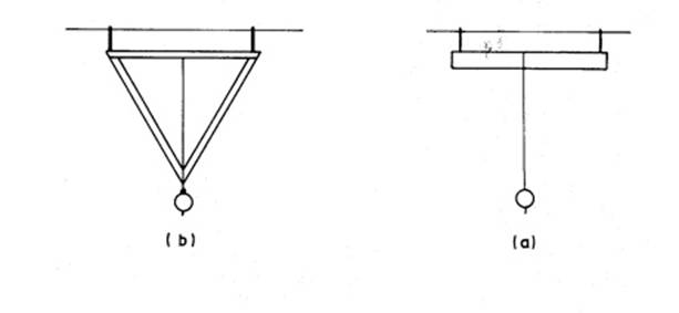
Fig. 4
For setting out straight lines and for measuring distances ropes were
used, with knots at intervals to mark the dimensions. A rotatable
alidade, provided with sighting holes and mounted on a plane surface,
could also be used for alignment. The astrolabe, which we shall meet in
a later section as an instrument for astronomical observation and
computation, was also widely used for land surveying. Here we are
concerned only with the back of the instrument, which consisted of an
alidade turning about a central pivot, its ends moving over a graduated
circle, each quadrant of which was divided into 90 degrees. In the lower
half of the face was a rectangle, one side of which was divided radially
into decimals, the other side into duo-decimals (see Figure 5).
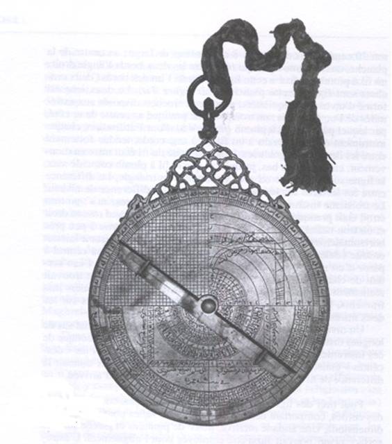
Fig. 5
The instrument was used for alignment and measuring the angles between
two points, but a number of Arabic writers also describe the solution of
various triangulation problems using the astrolabe. The two matching
squares into which the rectangle is divided are used for this purpose.
Although the squares are divided into ten and twelve equal parts
respectively, the choice of number is purely a matter of convenience.
With the astrolabe freely suspended the alidade is adjusted so that a
distant object is viewed through the sights simultaneously. When this
happens the real right-angled triangle formed by the distance of the
object and its height is reproduced on a small scale within the confines
of one square on the astrolabe, by an exactly similar right-angled
triangle. The real and similar triangles have a common line for
hypotenuse. The ratio of the lengths of the sides of the triangle on the
astrolabe is the same as the ratio of the height and distance of the
object, so that if either of these is known the other may readily be
calculated. If neither is known, the observer reads the angle from one
station, moves back a measured distance, and again reads the angle.
Since the Muslims had perfected the methods of both plane and spherical
trigonometry, problems of this sort could easily be solved. For the
surveyor in the field, however, it was clearly preferable to use the
constructive methods provided by the astrolabe, and manuals for his use
were prepared by scientists. Other problems solved by the use of the
astrolabe included finding the width of a river, or the distance between
two points separated by an impassable obstruction.
Part Two
MECHANICAL
ENGINEERING
Water-raising
machines
The earliest machine used by man for irrigation and water supply is the
shaduf. It is illustrated as early as 2500 B.C.E in Akkadian
reliefs and about 2000 B.C.E. in Egypt. It has remained in use until the
present day and its application is world-wide, so that it is one of the
most successful machines ever invented. Its success is probably due to
its simplicity, since it can easily be constructed by the village
carpenter using local materials. For fairly low lifts it delivers
substantial quantities of water. It consists of a long wooden pole
suspended at a fulcrum to a wooden beam supported by columns of wood,
stone or brick. At the end of the short arm of the lever is a
counterweight made of stone or, in alluvial areas where stone is not
available, of clay. The bucket is suspended to the other end by a rope
(see Figure 6). The operator lowers the bucket into the water and allows
it to fill. It is then raised by the action or the counterweight and its
contents are discharged into an irrigation ditch or a head tank.
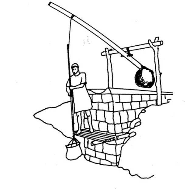
Fig.
6
The scoop drum or tympanum was probably invented in Egypt in the
first half of the third century B.C.E. Two large timber discs were fixed
to a wooden axle which had iron pegs protruding from its ends. The pegs
were housed in iron bearings supported on two columns. The space between
the discs was divided into eight segments by wooden boards. The
perimeter was closed by wooden boards, there being a slot in each
segment to receive the water. Circular holes were cut around the axle in
one face of the drum, one hole to each segment. The whole machine was
coated with tar (see Figure 7). As the drum was rotated by a
tread-wheel, the water was scooped from the source, entered the
compartments when they were at the bottom of their travel and was
discharged from them when they approached the top. The water ran into a
channel and then into a head tank. The scoop drum is rarely mentioned by
Muslim writers in connection with irrigation, and its main use seems to
have been in de-watering mines. It is ideally suited for this purpose
since it can be operated in a fairly restricted space. It was necessary
to use a series of drums: the first raised the water into a tank on a
platform, a second wheel raised it from this tank to a second tank and
so on, until the water was discharged into a drain at the head of the
mine.
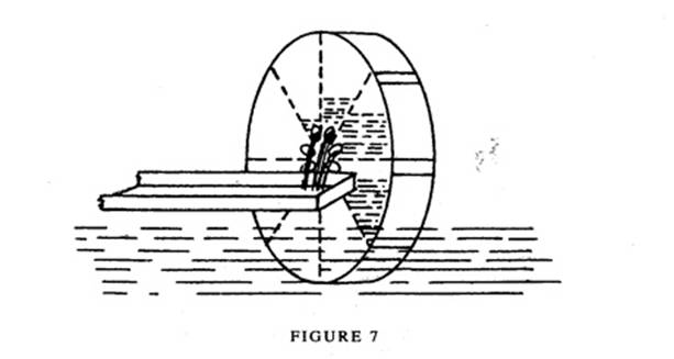
Fig 7
The screw or water-snail was probably invented by Archimedes (c.
287-212 B.C.E.) when he was living in Egypt and it is therefore
appropriate that the machine is often called the ‘Archimedean screw’. A
wooden blade is fitted spirally to a long cylindrical wooden rotor. A
wooden case is made to fit around the blade, constructed like a barrel,
the planks painted with pitch and bound with iron hoops. The rotor is
supplied with iron spigots which rotate in iron journals. The screw is
set at an angle with one of its ends in the water and as it is rotated
the water flows along the helix and discharges from the other end. The
smaller the angle to the horizontal, the greater will be the rate of
discharge. We do not know precisely how the machine was turned in
earlier times – it may have been by a tread-wheel, the power transmitted
through a pair of gears. Nowadays it is usually operated by a crank, but
the crank is not known to have been in use before the sixth/twelfth
century. The screw was in common use throughout the Muslim world until
quite recently, but now seems to be becoming rarer (see Figure 8).
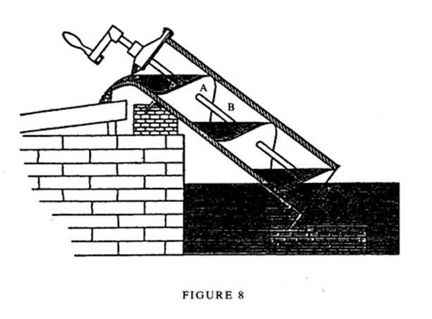
Fig 8
The word saqiya is used here to denote the chain-of-pots driven
through a pair of gear-wheels by one or two animals harnessed to a
draw-bar and walking around a circular track. This very important
machine was invented in Egypt, probably about 200 B.C.E., but did not
come into widespread use until the fourth or fifth century C.E., with
the introduction of the pawl mechanism and earthenware pots. Although it
is fairly easy to explain the operation of the machine, it should be
emphasized that its construction is quite complex, consisting as it does
of over 200 separate components. Only the basic constructional details
will be given here. The draw-bar to which the animal is harnessed passes
through a hole in an upright shaft to which the horizontal gear -wheel
is fixed by spokes. The shaft rotates in a thrust bearing at ground
level and another bearing above the gear -wheel located in a cross-beam
which is supported on plinths. The gear-wheel is a lantern-pinion, i.e.
two large wooden discs held apart by equally spaced pegs. The vertical
gear- wheel carries the chain-of-pots and is often called the potgarland
wheel. It is supported centrally over the well or other source of water
on a wooden axle. On one side of it are the pegs that enter the spaces
between the pegs of the lantern-pinion and these pegs pass through to
the other side of the wheel, where they carry the chain-of-pots. This
consists of two continuous loops of rope between which the earthenware
pots are attached – sometimes chains and metal containers are used
(Figure 9). In order to prevent the wheel from going into reverse, the
machine is provided with a pawl mechanism, which acts on the cogs of the
potgarland wheel. This mechanism is essential, because the draught
animal is subjected to a constant pull both when moving and when
standing still. The pawl is activated in two cases – when the animal is
to be unharnessed and in the event of the harness or traces breaking.
Without the pawl the machine would turn backwards at great speed and,
after one revolution, the drawbar would hit the animal on the head. At
the same time, many of the pins of the lantern - pinion would break and
the pots smash.
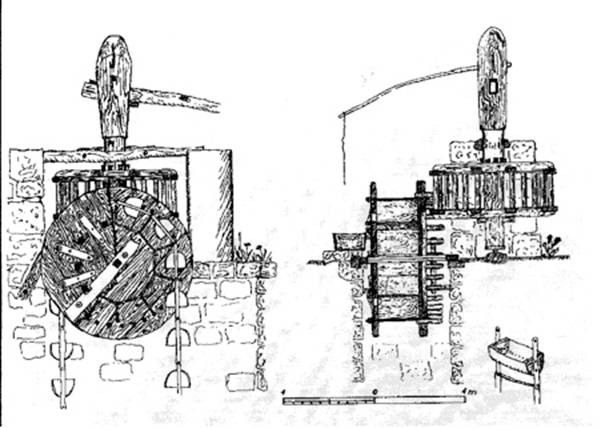
Fig. 9 –
A saqiya at Ma’arrat al-Nu’man near Aleppo, Syria
As the animal walks in a circular path, the lantern-pinion is turned and this rotates the potgarland wheel. The pots dip into the water in continuous succession and discharge at the top of the wheel into a channel connected to a head tank. Although the main function of the saqiya is for irrigation it can also be important for water supply when, for example, buildings are some distance above the source of water. The longer the chain-of-pots, i.e. the lift, the lower the rate of discharge will be. For domestic water supply this may not be a crucial factor, but in fact one of the problems of water-raising engineering is that of raising large quantities of water through a small lift. The problem can be solved by using a spiral scoop-wheel (see Figure 10), which raises water to ground level with a high degree of efficiency. This machine is very popular in Egypt nowadays, and engineers at a research station near Cairo have been trying to improve the shape of the scoop in order to achieve maximum output. Although it appears very modern in design, this is not the case, since a miniature from Baghdad dated to the sixth/twelfth century shows a spiral scoop-wheel driven by two oxen. The transmission of power is the same as that employed with the standard saqiya.
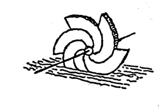
Fig. 10
The saqiya was widely used in the Muslim world from the earliest
days onwards. It was introduced to the Iberian peninsula by the Muslims,
where it was massively exploited. Not only was it diffused into many
parts of Europe but it was also taken to the New World by Christian
Spanish engineers. It has advantages over the diesel-driven pump: it can
be constructed and maintained by local craftsmen and does not require
the importation of fuel. The long history of the saqiya is by no
means ended, and there are welcome indications that its advantages will
ensure its survival for the foreseeable future.
The noria is also a very significant machine in the history of
engineering. It consists of a large wheel made of timber and provided
with paddles. The rim of the wheel, inside the paddles, is divided into
compartments or, in another type of noria, earthenware pots
similar to those of the saqiya, are lashed to the rim. The wheel
is mounted on an axle over a running stream, so positioned that the
paddles and the compartments, at the lowest part of their travel, are
immersed in the water. The force of the current acting on the paddles
causes the wheel to rotate, the compartments fill with water and
discharge their contents when they reach the top of the wheel. The water
usually collects in a head tank and is then conducted through a feeder
channel to the irrigation system or to an urban water supply (see Figure
11). Being driven by water, the noria is self-acting and requires
the presence of neither man nor animal for its operation.
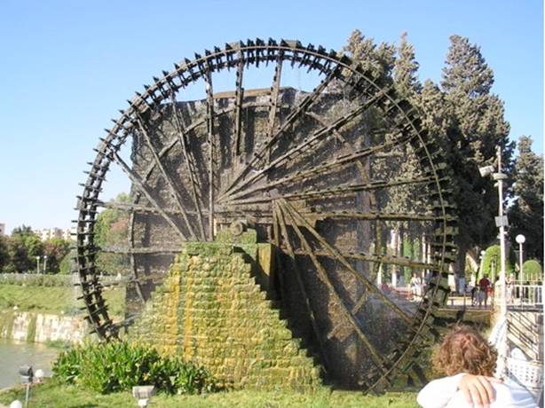
Fig. 11 –
Noria at Hama, Syria
The earliest description we have of the noria occurs in the
writings of Vitruvius in the first century B.C.E., in words that imply
that it had already been in use for some time. It was invented around
200 B.C.E. in the Near East. Its use was widespread in the Muslim world,
wherever conditions were appropriate; there are attestations for its use
in Iraq, Iran, Mesopotamia, Spain and elsewhere. The most famous
norias are those at Hama, on the River Orontes in Syria. These are
an impressive sight, the largest being over 20 metres in diameter; they
discharge into the end of an aqueduct that carries the water to the town
and the fields. These machines are known to have been in operation since
the third/ninth century, but there were probably norias at this
site much earlier than this. The large-scale use of norias was
introduced to Spain by Syrian engineers. An installation similar to that
at Hama was in operation at Toledo in the sixth/twelfth century and the
machine was heavily exploited all over Muslim Spain. It was diffused to
other parts of Europe and to East Asia, and like the saqiya has
shown remarkable powers of survival into modern times.
Five water-raising machines are described in al-Jazari’s great book on
machines, composed in Diyar Bakr in 602/1206. One of these is a
water-driven saqiya, a type of machine that is known to have been
in everyday use in medieval Islam. Three of the others are modifications
to the shaduf, obviously intended to raise the output of the
traditional machine. These are important for the ideas they embody,
ideas which are of importance in the development of mechanical
engineering. In one of them, for example, the concept of minimising
intermittent working is implied and another incorporates a crank, the
first known example of a crank used as an integral part of a machine.
The fifth machine is the most significant. This is a water-driven
twin-cylinder pump (Figure 12). A paddle wheel is mounted on a
horizontal axle over a running stream, with a gear-wheel mounted on the
other end of the axle. This meshes with a horizontal gear-wheel
installed in a large triangular wooden box which is mounted over a pond
supplied from the stream. On the face of the second gear-wheel, near the
outside, is a peg which enters a slot-rod pivoted at one corner of the
box. The connecting rods were fixed to the sides of the slot-rod by
staple-and-ring fittings. On the end of each connecting rod was a
piston, consisting of two copper discs with a space of about 6 cm
between them, the space filled by coiling hempen cord until the gap was
filled. The cylinders, made of copper, were provided with suction and
delivery pipes, all provided with non-return clack-valves. The two
delivery pipes were joined together above the machine to form a single
delivery pipe, which discharged the water at a height of about 14 m
above the level of the stream. The action was as follows: when the
paddle wheel turned it caused the gear-wheel on its axle to turn, and
this rotated the gear-wheel in the box and the peg made the slot-rod
oscillate from side to side. When one piston was on its delivery stroke
the other was on its suction stroke. The important features embodied in
this pump are the double-acting principle, the conversion of rotary into
reciprocating motion, and the use of true suction pipes. The hand-driven
pumps of classical and Hellenistic times had vertical cylinders which
stood directly in the water which entered them through plate-valves in
the bottoms of the cylinders on the suction strokes. The pumps could
not, therefore, be positioned above the water level. A quarter-scale
working model of this pump was made for the 1976 World of Islam Festival
in the Science Museum, London. The construction is the same as that of
the machine described by al-Jazari, except that the drive was electric.
The pump works perfectly, with smooth transmission and the discharge of
a steady stream of water from the delivery pipe.
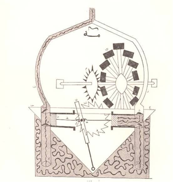
Fig 12
-Al-Jazari’s two cylinder suction pump
Evidence for the continuation of a tradition of mechanical engineering
is provided by a book on machines written by Taqi al-Din about the year
959/1552. A number of machines are described, including a pump similar
to al-Jazari’s, but the most interesting device is a six-cylinder
‘Monobloc’ pump. The cylinders are bored in line in a block of wood
which stands in the water – one-way valves admit water into each
cylinder on the suction stroke. The delivery pipes, each of which is
also provided with a one-way clack-valve, are led out from the side of
each cylinder and brought together into a single delivery outlet. On the
end of each piston rod is a lead weight, and a trip lever is connected
by a pin joint to the piston rod just below the weight. Cams on the axle
of a water-driven scoop-wheel bear down on the trip levers in succession
raising the pistons for the suction stroke. When the trip lever is
released the weight forces the piston down for the delivery stroke (see
Figure 13). It is worthy of note that Taqi al-Din’s book antedates the
famous book on machines written by Agostino Ramelli in 1588. It is
therefore quite possible that there was some Islamic influence on
European machine technology even as late as the tenth/sixteenth century.[24]
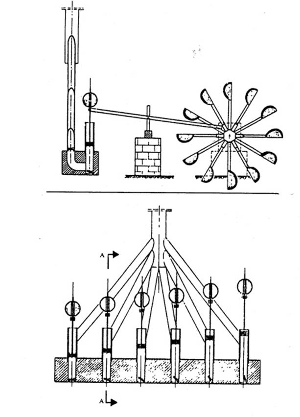
Fig. 13 – Taqi al-Din’s six cylinder pump
Power
from water and wind
There are three basic types of water-wheel, all of which had been in use
for centuries before the advent of Islam and the question of their
origin, and diffusion, which is still unresolved and controversial, need
not concern us here. The first – the undershot wheel – is a paddle wheel
mounted on a horizontal axle over a running stream (Figure 14a). Its
power derives almost entirely from the velocity of the water, and it is
therefore affected by seasonal changes in the rate of flow of the stream
over which it is erected. Furthermore, the water level may fall, leaving
the paddles partly or totally out of the water. The efficiency of the
undershot wheel is not high perhaps as low as 22 per cent – because so
much of the energy is dissipated by turbulence and drag. The fact that
it retained its popularity over many centuries is due to the simplicity
of its construction and to special measures that can be taken to
increase its performance. These will be discussed later.
The overshot wheel is also vertical on a horizontal axle. Its rim is
divided into bucket-like compartments into which the water discharges
from above, usually from an artificial channel or ‘leat’ (see Figure
14b). Its efficiency can be as high as 66 per cent, provided all the
water from the leat falls into the buckets and there is no spillage.
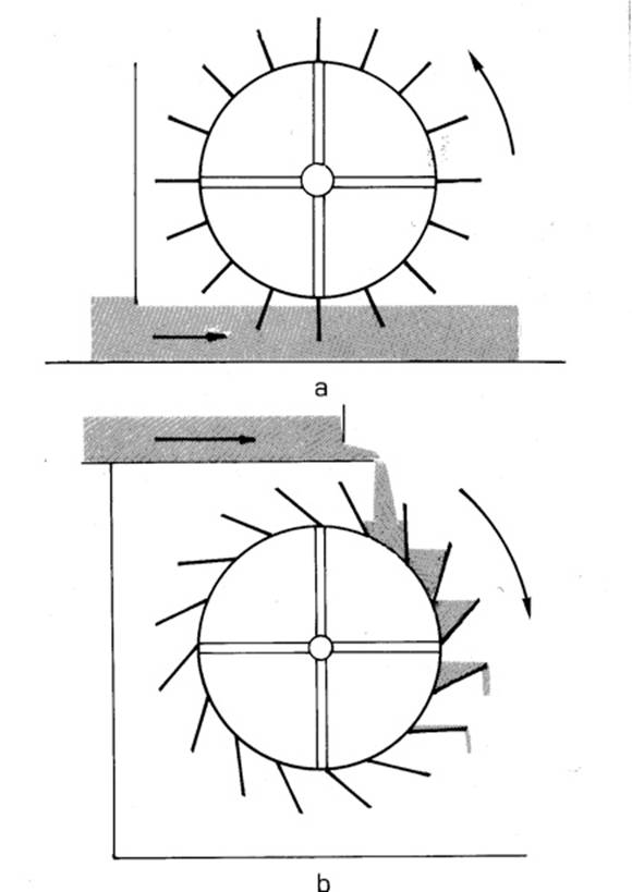
Fig 14 a
and b
When used for corn milling, both types of vertical wheels require a pair
of gears to transmit the power to the millstones. A vertical toothed
wheel is mounted on the end of the water-wheel’s axle inside the mill
house. This engages a lantern-pinion, whose vertical axle goes up
through the floor to the milling room; it passes through the lower,
fixed millstone and is fixed to the upper, rotating stone. The corn is
fed into the concavity of the upper stone from a hopper (see Figure 15).
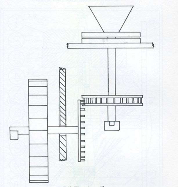
Fig. 15
The third type of wheel is horizontal, and can be subdivided into two
main types. In the first of these a wheel with curved or scooped vanes
is mounted at the bottom of the vertical shaft and water from an orifice
fitted to the bottom of a water tower is directed on to the vanes, the
flow being therefore tangential and radial (Figure 16). The second type
is a vaned wheel, also fixed to the lower end of a vertical axle, and
installed inside a cylinder into which the water cascades from above,
turning the wheel mainly by axial flow. Axial-flow wheels can also be
driven by vertical jets of water directed on to them from below. The
first sub-type was known in Europe and western Asia by the sixth century
C.E. at the latest. The second appears in an Arabic treatise of the
third/ninth century, but is not known to have been used in Europe before
the tenth/sixteenth century.
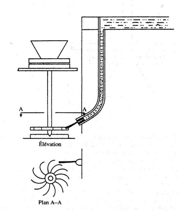
Fig. 16
The Muslim geographers and travellers leave us in no doubt as to the
importance of corn-milling in the Muslim world. This importance is
reflected not only in the widespread occurrence of mills, from the
Iberian peninsula to Iran, but also in the very positive attitude of the
writers to the potential of streams for conversion to power. The Tigris
at its source, says al-Muqaddasi, would turn only one mill, and
al-Istakhri looking at a fast-flowing stream in the Iranian province of
Kerman, estimates that it would turn twenty mills. It is as if these
travellers were rating streams at so much ‘mill-power’. This concern is
understandable when we remember that the great cities of Islam such as
Baghdad, Fustat and Cordoba depended upon the produce of a thriving
agriculture to feed their large populations and to provide the finished
materials for a thriving commerce. We therefore find that all large
urban communities were provided with flour by factory milling
installations, either close to the city or accessible to it by good
communications. To take but one example: in the fourth/tenth century
Upper Mesopotamia was the granary for Baghdad and the corn it produced
was ground in large ship-mills moored on the Tigris and the Euphrates.
Each mill had two pairs of stones and could produce 10 tonnes of flour
in 24 hours. Nothing approaching this scale of corn-milling was known in
contemporary Europe.
The
ship-mill was one of the methods used to increase the output of mills,
taking advantage of the faster current in midstream and avoiding the
problems caused by the lowering of the water level in the dry season.
Another method was to fix the water-wheels to the piers of bridges in
order to utilize the increased flow caused by the partial damming of the
river. Dams were also constructed to provide additional power for mills
(and water-raising machines) such as the dam built by ‘Adud al-Dawla
over the River Kur in Iran. In the sixth/twelfth century al-Idrisi
described the dam at Cordoba in Spain, in which there were three mill
houses each containing four mills. Until quite recently its three mill
houses still functioned, but have changed a lot from their original
form. Further evidence of the Muslims’ eagerness to harness every
available source of water power is provided by their use of tidal mills.
This application is, of course, not possible in the Mediterranean, but
in the fourth/tenth century in the Basra area there were mills that were
operated by the ebb-tide. Tidal mills did not appear in Europe until
about a century after this.
Water power was also used in Islam for other industrial purposes.. It
seems that the use of water power in industrial applications was already
established at an early date. Jabir Ibn Hayyan (b.721- d.815 C.E.) in
Kitab al-Sab’in (Book of the Seventy) describes in treatise
XVIII a spherical vessel for melting metals. This sphere was erected on
a river and it was rotated by a water wheel. The sphere rotated
continuously while it was heated by fire from underneath it.[25]
Jabir describes a similar continuous rotating motion on a river in
treatise XXXIV of the same book.[26]
In the year 134/751, after the battle of Atlakh or Talas, Chinese
prisoners of war introduced the industry of paper-making in the city of
Samarkand. The paper was made from linen, flax or hemp rags. Soon
afterwards paper mills on the pattern of those in Samarkand were erected
in Baghdad, the Yemen, Egypt, Syria, Iran, North Africa and Spain.
Without doubt, the raw materials in these mills were prepared by
pounding them with water-powered trip-hammers. Writing about the year
435/1044, al-Biruni tells us that gold ores were pulverized by this
method “as is the case in Samarkand with the pounding of flax for
paper”. Water power was also used in the Muslim world for fulling cloth,
sawing timber and processing sugarcane. (It is interesting to note that
the transfer of technology between China and Islam was a two-way
traffic; according to Marco Polo, the Muslims taught the Chinese how to
refine sugar.) It has not yet been established to what extent industrial
milling in Europe was influenced by Muslim practices. A likely area of
transfer is the Iberian Peninsula, where the Christians took over, in
working order, many Muslim installations, including the paper mills at
Jativa.
Windmills were probably known in Seistan (the western part of modern Afghanistan) before the advent of Islam. According to al-Mas’udi, a Persian claimed to the Caliph ‘Umar I that he was able to build a windmill. ‘Umar made him substantiate his claim by building one. Mills in Seistan are mentioned by the Arab geographers of the fourth/tenth century, but the first full description occurs in a book written about the year 669/1271[27]. These were not the European type of windmill with a horizontal axle and a pair of gears. The mills were supported on substructures built for the purpose, or on the towers of castles or on the tops of hills. They consisted of an upper chamber in which the millstones were housed and a lower one for the rotor. The axle was vertical and it carried twelve or six arms covered with sails. The walls of the lower chamber were pierced with funnel-shaped ducts, with the narrower end towards the interior in order to increase the speed of the wind when it flowed on to the sails (Fig. 17). This type of windmill spread throughout Islam, and to China and India. In medieval Egypt it was used in the sugar-cane industry, but its main application was to corn-milling.
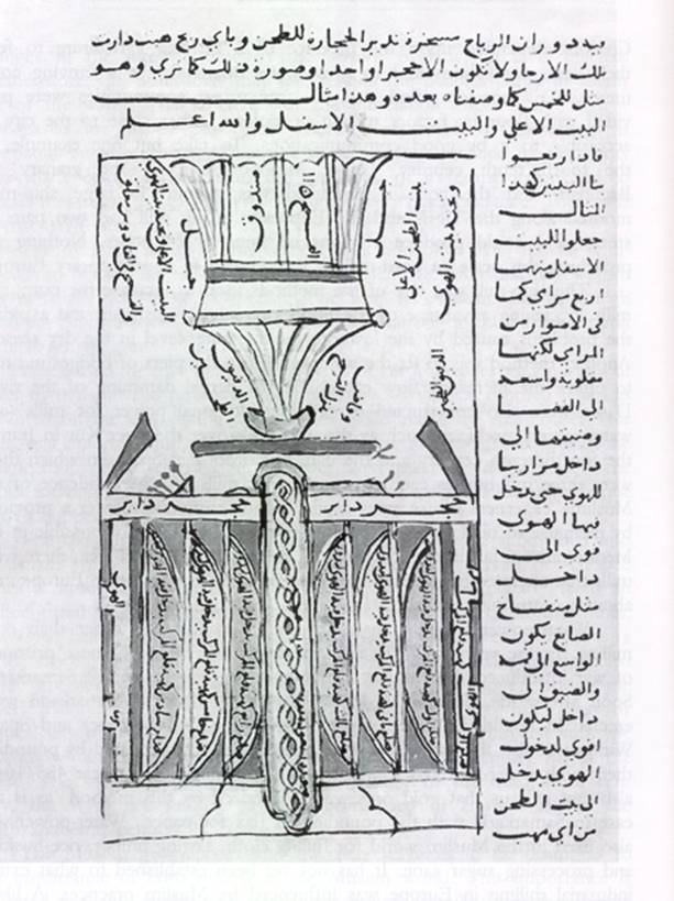
Fig. 17 – Wind mill in Seistan as described by al-Dimashqi
FINE TECHNOLOGY
The expression ‘fine technology’, applied to earlier times, embraces a
whole range of devices and machines, with a multiplicity of purposes:
water clocks, fountains, toys and automata and astronomical instruments.
Some were designed to tell the time, as aids to scientific investigation
and some to delight and amuse. What they have in common is the
considerable degree of engineering skill required for their manufacture,
and the use of delicate mechanisms and sensitive control systems. Many
of the ideas employed in the construction of ingenious devices were
useful in the later development of mechanical technology.
When we look into the origins of fine technology, we inevitably find our
attention directed to the Hellenistic world and, in particular,
Alexandria. Thus we find that the first complex water clock and the
first musical automaton are both attributed by Vitruvius to Ctesibius,
an Egyptian engineer who worked in Alexandria about 250 B.C.E, and the
first major treatise on ingenious devices was composed by Philon of
Byzantium a contemporary of Ctesibius. Philon’s work was continued and
extended by Heron of Alexandria, who flourished in the middle of the
first century C.E. The origins of the astrolabe can be firmly placed in
the school of Alexandria. It was almost certainly known to Ptolemy and
was described by Theon of Alexandria (c. 350 C.E.), whose writings are
preserved in the treatise of Severus Sebokht, who composed his book in
Kinnesrin in the north of Syria before 660 C.E. i.e. a few years after
the Arab rule..
The tradition of fine technology continued uninterrupted and was further
developed under Islam. Monumental water clocks in Syria continued to be
installed in public places. The Abbasid Caliphs were interested in
clocks and ingenious devices. The story of the clock that was presented
by Harun al-Rashid (786-809), to
Charlemagne in 807 C.E. is well known.[28]
It is reported also by Ibn Abi Usaybi’a that Al-Mutawakkil (d. 861) was
so obsessed with ingenuous devices, literally Alat mutaharrika
(moving machines), that he favoured the Bani Musa who took advantage of
the Caliph’s obsession and persecuted their opponents..[29]
The Banu Musa wrote their book on al-Hiyal during this period,
and we infer from this story that they had actually constructed and
operated their devices to please and satisfy the Caliph. In Kitab
al-hayawan, al-Jahiz (776-867 C.E.) when discussing the
measurement of time, says: ” Our kings and scientists use the astrolabe
by day and the binkamat (clocks) by night”[30]
It is reported also by historians that Nasir al Dawla of Diyar
Bakr (d. 1061 C.E.) had constructed a public binkm (clock) for
the city of Mayyafariqin in the year 1012 C.E.[31]
When al-Jazari wrote his book 200 hundred years later in Diyar
Bakr, he was describing a tradition that was firmly established in that
area. Other clocks in public places were installed in some other cities
of the Islamic east.
The technology of clock-making was transferred to
Muslim Spain and to Al-Maghrib. About the year 1050 C.E. al-Zarqali
constructed a large water clock on the banks of the Tagus at Toledo in
Spain. The clock was still in operation when the Christians occupied
Toledo in 1085 C.E. A manuscript describing Andalusian monumental clocks
was written in the eleventh century by Ibn Khalaf al-Muradi.
[32] Water clocks were constructed
for public places in al-Maghrib. The remains of a public water clock in
Fas can still be seen.[33]
In Damascus, Muúammad al-Khurasani al-Sa’ati (the
clockmaker) built a monumental clock around 1160. The clock was
described by several travellers, It was still in operation when Ibn
Batuta visited Damascus in the 14th century.[34]
Ridwan al-Sa’ati, the son of the clock’s maker, re-built the clock and
gave a detailed description of its construction in 1203.
Al-Jazari’s book was written in Amid, Diyar Bakr, in 1206. This
book together with Kitab al-hiyal of Bani Musa, are the most
important treatises on fine technology that came down to us. It is
reported also that the astronomer ‘Ali al-Qushji (d. 1474) wrote a
tadhkira or treatise on spiritual machines[35].
The last important writer on the same subject was Taqi al-Din ibn Ma’ruf
al-Dimashqi who wrote a book on water clocks in 1552 and another on
mechanical clocks in 1556.
[36]
In addition to water clocks and ingenious devices, the
making of astrolabes and of geared astronomical mechanisms in Islam
continued throughout the centuries as will be shown later. Our knowledge
of Islamic fine technology will continue to improve with the publication
of more research results.
It is not easy in the space available to demonstrate
the achievements of Muslim engineers in the field of fine technology.
This can probably best be done by considering a few of the more
important Islamic works, placing emphasis upon their innovative
features. The Banu Musa were three brothers – Muhammad, Ahmad and
al-Hasan – who were members of the courtly circles of the Abbasid Caliph
al-Ma’mun (198/813-218/833) and his successors. This was the period that
witnessed the first flowering of Arabic science, both in the translation
of Greek and Syriac works into Arabic and in original scientific and
technological works, and much of this activity was carried out under the
direction and patronage of the Banu Musa. They were also scientists and
engineers in their own right and wrote about twenty treatises, only two
of which are known to have survived. One of these, The Book of
Ingenious Devices (Kitab al-hiyal), written in Baghdad
about 235/850, is our present concern[37].
It contains descriptions of a hundred devices, most of which are trick
vessels, together with self-feeding and self-trimming lamps, a gas mask
for use in polluted wells and a mechanical grab. The trick vessels
exhibit a bewildering variety of effects, for example:
Model 26. A jar with an outlet pipe: during inpouring of a liquid the
pourer can, according to choice, allow the liquid to discharge, or
prevent its discharging.
Model 43. A jar with a tap, into which three different liquids can be
poured without mixing. When the tap is opened the liquids discharge in
the sequence in which they were poured in.
Model 77. A basin beside a closed reservoir. When moderate quantities of
water are taken from the basin, like quantities run into it from a pipe
at the bottom of the reservoir; if, however, a large quantity is taken
no replenishment occurs.
These effects, and many others, were produced by the ingenious
combination of a number of hydraulic and mechanical components, two of
which are shown in Figure 18. Figure 18(a) shows a double concentric
siphon: pipe bd passes through plate f which divides the
upper chamber from the lower, the joint being airtight. Pipe a-cc
is placed over end b of pipe bd and held to it by
soldering pieces of copper wire between the two pipes. End a of
this pipe is closed. Another wide piece of pipe e-gg, its end
e closed, is fixed over end d of pipe bd. The effect
of introducing this device into a flow system is to create an airlock
once the flow of liquid is interrupted, so that the flow cannot be
restarted except under certain conditions. Onlookers could therefore be
startled by unexpected events. The double concentric siphon does not
occur in any of the Greek writings nor, as far as we know, in any Arabic
work except the Banu Musas book. The fluid mechanics of its operation
are surprisingly complex.
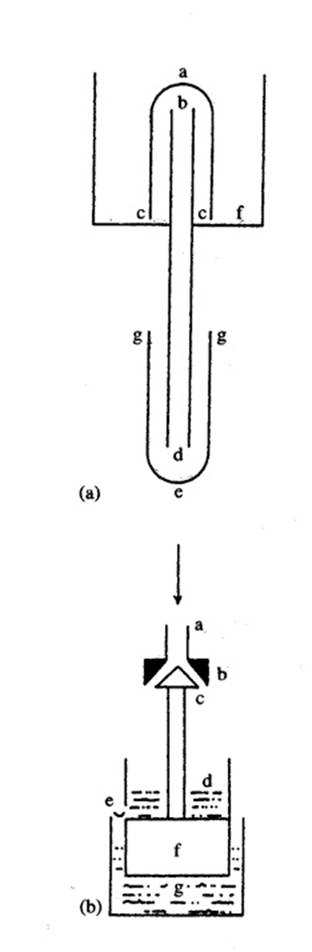
Fig. 18 a
and b
The second mechanism is shown in Figure 18 (b). Seat b of a
conical valve is soldered to the end of pipe a, and plug c
of the valve is soldered to the end of a vertical rod, the other end of
which is soldered to the top of float f. Above the float and
integral with it is the small tank d which has a small hole e
in the bottom of one of its sides. The float rests on the surface of the
water in the slightly larger tank g. It works like this: water is
poured in at a and runs through the valve into tank d; the
weight of the liquid in tank d stops the valve-rod from rising
and so the valve remains open. When pouring is stopped tank d
empties into tank g through hole e, float f rises
and the valve closes. No further inpouring can then take place. Conical
valves do not appear in the works of Philon and Heron. They were made by
casting the plug and seat together in a single mould, the material
nearly always being bronze. Plug and seat were then ground together with
emery powder to a watertight fit.
A distinguishing feature of the Banu Musa’s work is therefore their
confident use of conical valves as integral parts of flow systems. More
generally, they show an astonishing empirical mastery of the use of
small variations in hydrostatic and aerostatic pressures to produce a
variety of effects. Although their work was well-known in the Muslim
world for centuries after their time, none of their successors ever
attempted to emulate them. They had, in fact, taken the subject to its
limits with the materials and techniques then available, and nothing
similar was done until the introduction of pneumatic instrumentation in
modern times.
A most important treatise was written in Muslim Spain in the
fifth/eleventh century by al-Muradi. Unfortunately, the only known
manuscript of the work is so badly defaced that it is impossible to
deduce from it precisely how any of the machines was constructed. Most
of the devices were water clocks, but the first five were large automata
machines that incorporated several significant features. Each of them,
for example, was driven by a full-size water wheel, a method that was
employed in China at the same period to drive a very large monumental
water clock. The automata were of the types that were common in water
clocks, for example a set of doors in a row that open at successive
intervals to reveal jackwork figures. The text mentions both segmental
and epicyclic gears. (In segmental gears one of a pair of meshing
gear-wheels has teeth on only part of its perimeter; the mechanism
permits intermittent transmission of power). Although the illustrations
are in other respects quite incomprehensible, they clearly show
gear-trains incorporating both these types of gearing. This is extremely
important: we have met simple gears in mills and water-raising machines,
but this is the first known case of complex gears used to transmit high
torque. It is also the earliest record we have of segmental and
epicyclic gears. Sophisticated gears for transmitting high torque, first
appeared in Europe in the astronomical clock completed by Giovanni de’
Dondi about 1365.C.E.
Al-Jazari completed his magnificent book on machines in Diyar Bakr in
the year 602/1206.[38]
This is the most remarkable engineering document to have come down to
us, from any cultural area, until the Renaissance. In one respect it is
unique: it was written at the wish of al-Jazari’s master, the Artuqid
Sultan Nasir al-Din Mahmud ibn Muhammad,
so that a record of the fragile devices could be available for
succeeding generations of craftsmen, long after the devices themselves
had perished. Each of the fifty chapters – text and illustrations – was
therefore composed with detailed instructions for manufacture, so that
the machines could be reconstructed by later craftsmen; Al-Jazari was
successful in this aim because several of his devices including a
monumental water clock, have been constructed by modern craftsmen
working from al-Jazari’s instructions. The works of other writers, while
they often describe the operation of the machines quite adequately, give
only the sketchiest details of construction. Al-Jazari’s willingness and
ability to communicate the knowledge gained by training, experience and
informed experiment therefore endow his work with immense value.
AI-Jazari was an engineer who took pride in continuing a long tradition
of mechanical technology, and his work may in many respects be regarded
as the epitome and the summit of the Islamic achievement in this field.
With one or two notable exceptions, such as the complex gear-trains of
al-Muradi, it is safe to assume that he dealt with most of the machines
that had been known to his predecessors, while introducing innovations
and improvements of his own. Indeed, he often acknowledges the work of
earlier engineers, such as Archimedes or the Banu Musa in connection
with a particular technique or type of machine, describes the earlier
construction accurately and then tells us how he improved upon it. For
instance, a certain type of flow regulator was used in water clocks by
both Hellenistic and Muslim engineers. Al-Jazari found by experiment
that it was inaccurate, and describes how he made an accurate instrument
by carefully calibrating a small orifice to produce correct rates of
flow under various heads of water.
One example will have to suffice to give some idea of al-Jazari’s
methods and the type of devices he constructed. This is the water
machinery and some of the associated mechanisms from his third and
fourth water clocks. These were driven by the submersible bowl or
tahrajar a device that was normally used for timing the period of
allocation of irrigation water to farmers. These two clocks are the only
examples we have of the adaptation of the tahrajar for
timekeeping, and it seems likely that this system was al-Jazari’s own
invention. Figure 19 shows the basic principles; it would be impossible
to describe either of the clocks fully, since they had a number of
automata together with the mechanisms for activating them, some of them
very ingenious.
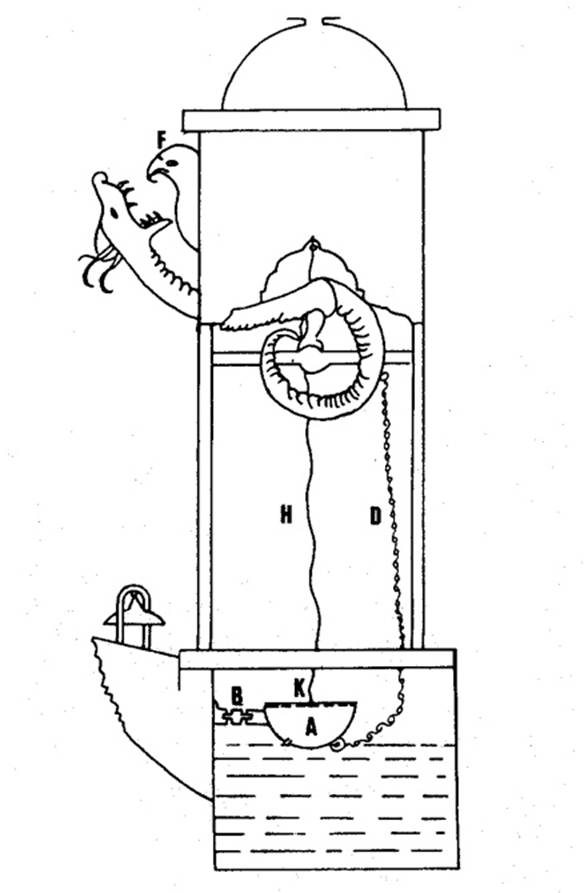
Fig. 19
The bowl A with a calibrated orifice in its underside rests on
the surface of the water in tank N, to which it is connected by
the three flat pin-jointed links H. A rod is soldered across a
diameter of the bowl, with hole K in its centre. At the top of
the clock, supported on four columns, is the ‘castle’, a square brass
box with a detachable dome. Inside the castle is a ball-release
mechanism (not shown) from which a channel leads to the head F of
a bird. The tail of the serpent, in effect a pulley, rotates on an axle
that rests in bearings in transoms fixed between each pair of columns.
The open mouth of the serpent is just below the head of the bird. A
light chain D runs from the underside of the bowl to a staple in
the tail of the serpent. A wire H is tied to hole K and to
the ball-release. At the beginning of a time period – an hour or half an
hour – the empty bowl is on the surface of the water. It sinks slowly
until at the end of the period it suddenly submerges. Wire H
operates the ball-release, and a ball runs into the bird’s mouth and out
of its hinged beak into the mouth of the serpent. The serpent’s head
sinks, and chain D lifts the bowl, which tilts due to the
combined action of the chain and links B and discharges all its
contents. The ball drops from the serpent’s mouth on to a cymbal, and
the serpent’s head rises to its previous position. The empty bowl is
again horizontal on the surface of the water, and the cycle re-starts.
This is therefore a closed-loop system, since the clock will continue
working as long as there are balls in the magazine. The concept of
continuous operation occurs elsewhere in al-Jazari’s work; in his first
clock, for example, the head of water over the orifice is kept constant
by a hydraulic feed-back control system.
A number of ideas and techniques appear for the first time in
al-Jazari’s work. These include the double-acting pump with suction
pipes and the use of a crank in a machine (both already mentioned);
accurate calibration of orifices; lamination of timber to minimize
warping; static balancing of wheels; use of paper models to establish a
design; and casting of metals in closed mould-boxes with green sand.
There is also an indication that he knew of a method for controlling the
speed of rotation of a wheel by an escapement of some kind. This is very
significant when we consider a clock described in a Spanish work
compiled in 1277 C.E. in which all the chapters are translations or
paraphrases of earlier Arabic works. The clock consisted of a large drum
made of walnut or jujube wood tightly assembled and sealed with wax or
resin. The interior of the drum was divided into twelve compartments,
with small holes between the compartments through which mercury flowed.
Enough mercury was enclosed to fill just half the compartments. The drum
was mounted on the same axle as a large wheel powered by a weight-drive
wound around the wheel. Also on the axle was a pinion with six teeth
that meshed with thirty-six oaken teeth on the rim of an astrolabic
dial. The mercury drum and the pinion made a complete revolution in 4
hours and the astrolabic dial made a complete revolution in 24 hours.
Clocks incorporating this principle are known to work satisfactorily,
since many of them were made in Europe in the seventeenth and eighteenth
centuries. This type of timepiece, however, with its effective mercury
escapement, had been known in Islam since the fifth/eleventh century, at
least 200 years before the first appearance of weight-driven clocks in
the West.[39]
The astrolabe was the astronomical instrument par excellence of
the Middle Ages; from its Hellenistic origins it was brought to
perfection by Muslim scientists and craftsmen. Essentially it consists
of a circular plate inside a raised annulus that is divided into
degrees, the annulus being soldered to the rim of a base-plate. The
first plate is engraved with the lines of azimuth and altitude for the
latitude of the observer. Turning on a central pin above the plate is
the rete or spider, made of open metalwork. This is essentially a star
map, the principal fixed stars appearing as holes or gemstones; there is
also a circle for the sun’s ecliptic. Rotating above the rete was an
alidade. Both plate and rete were marked out by stereographic
projection. The instrument was usually made of brass (see Figure 5). A
number of astronomical problems, which otherwise have to be solved by
tedious computation, can be solved very quickly by using the astrolabe.
It has been established that the first European treatises on the
astrolabe were of Arabic inspiration and were written in Latin at the
beginning of the fifth/eleventh century in the abbey of Ripoll in
Catalonia. From this centre the knowledge of the instrument was diffused
to the rest of Europe.
Other computing instruments were devised in the Muslim world in the
later Middle Ages, perhaps the most important of these being equatoria,
which were invented in Muslim Spain early in the fifth/eleventh century.
The objective of the equatorium was the determination of the longitude
of any one of the planets at a given time. This was done by constructing
to scale and by mechanical and graphical means the Ptolemaic
configuration for that particular planet at the given instant. As with
the astrolabe, knowledge of equatoria was diffused into Europe from the
Muslim world.
An important aspect of Islamic fine technology is the tradition of
geared astronomical instruments which were described in Arabic
literature. The most notable example is the astronomical geared
mechanism that was described by al-Biruni (Fig 20) and called by him
huqq al-Qamar (Box of the Moon).
[40] From al Biruni’s text we
understand that these mechanisms were known in Islamic astronomy. A
surviving example is the geared calendar made by Muhammad b. Abi Bakr
al-Ibari al-Isfahani dated 1221/2 C.E. which is found on the back of an
astrolabe. This instrument is in the collection of the Museum of the
History of Science at Oxford. The tradition of geared astronomical
instruments continued until later centuries and we find a description of
a geared mechanism in Taqi al-Din’s
Al-Turuq al-Saniyya (1552 C.E.) under the same name of
al-Biruni’s instrument: Huqq al-Qamar. Taqi al-Din says “as to
the method of use, there are special treatises for this purpose and we
need not elaborate on it here”
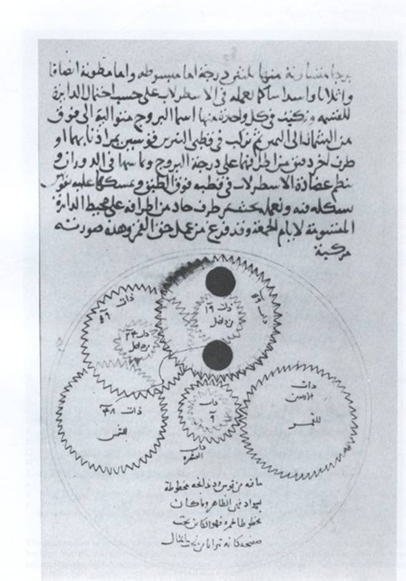
Fig. 20 –
Al-Biruni’s huqq al-qamar
Derek J. de Solla Price[41]
when describing the Antikythera mechanism (90 C.E.) remarked that " It
seems likely that the Antikythera tradition was part of a corpus of
knowledge that has since been lost but was known to the Arabs. It was
developed and transmitted by them to medieval Europe, where it became
the foundation for the whole range of subsequent invention in the field
of clockwork”
The
astronomical gearing mechanisms just mentioned were manually driven. But
as mentioned above, al-Muradi’s machine, (Model 5), shows a system of
gears for transmitting torque that is much more complex than any other
power-driven gears known to have existed so early.[42]
Many of the
ideas that were to be embodied in the mechanical clock had been
introduced centuries before its invention: complex gear trains,
segmental gears in al‑Muradi and al‑Jazari, epicycle gears in al‑Muradi,
celestial and biological simulations in the automata‑machines and water
clocks of Hellenistic and Islamic engineers; weight‑drives in Islamic
mercury clocks and. pumps, escapements in mercury docks, and other
methods of controlling the speeds of water wheels[43].
The heavy floats in water clocks may also be regarded as weights, with
the constant‑head system as the escapement.[44]
We know that
the Christians in Spain learned about Muslim water clocks, not only by
the translation of Arabic works into Spanish but also by the inspection
of actual clocks in Toledo. This knowledge was transferred to Europe and
there was a substantial advance in the fifth/eleventh century in the
techniques of hydraulic time-keeping. In a treatise written by Robertus
Anglicus in 1271, it is mentioned that the clockmakers – i.e. the makers
of water clocks – were trying to solve the problem of the mechanical
escapement and had almost reached their objective. The first effective
escapement appeared a few years later. This evidence, circumstantial
though it is, points strongly to an Islamic influence upon the invention
of the mechanical clock.
In the middle of the sixteenth century, mechanical clocks from Germany
and other European countries reached the Ottoman Empire. Taqi al-Din
wrote in 1556 C.E. his book Al-Kawakib al-Durriyya fi al-binkamat
al-Dawriyya (The Brightest Stars for the Construction of
Mechanical Clocks) in which he described a clock incorporating some
of his inventions[45].
He refers to the pocket watch (that uses a spring)[46]
from which we infer that they were quite common.
Select
Bibliography
(see
also the references in the footnotes)
Banu Musa,
Kitab al‑hiyal, critical
edition of the Arabic text by Ahmad.Y. al-Hassan, Aleppo, 1981,
Institute for the History of Arabic Science. English translation by
Donald R. Hill, The Banu (sons
of) Musa ibn Shakir, .The
Book of Ingenious Devices. (Kitab al-hiyal),
Dordrecht/Boston/London, 1979, Reidel Publishing Company.
Forbes, R.J.:
Studies in Ancient
Technology, 9 vol., Leiden, 1964‑1972, E.J. Brill
Glick, T.F.:
Irrigation and Society in
Medieval Valencia, Cambridge, Mass., 1970, Harvard University Press.
Goblot,
Henry: Les Qanats,
Mouton. Paris,1979.
al-Hassan, Ahmad
Y.: Taqi al-Din and Arabic
Mechanical Engineering, (in Arabic), Aleppo, 1976, University of
Aleppo Press.
al-Hassan, Ahmad
Y.and Donald R. Hill: Islamic Technology, An illustrated history,
CUP and UNESCO, 1986.
Hill, Donald .R.:
(1981): Arabic
Water‑clocks, Aleppo, 1981,
Institute for the History of Arabic Science, University of Aleppo.
(1984): A
History of Engineering in
Classical and Medieval Times, London, 1984, Croom Helm.
(1993): Islamic
Science and Engineering, Edinburgh, 1993.
(1998): Studies
in Islamic Technology, ed. by David King, Ashgate, 1998
al-Jazari (1):
A Compendium on the
Theory and Practice of the Mechanical Arts, Arabic text edited by.
Ahmad.Y. al-Hassan, Aleppo, 1979, Institute for the History of Arabic
Science, University of Aleppo.
al-Jazari: (2):
The Book of Knowledge of
Ingenious Mechanical Devices, Annotated English translation by
Donald R. Hill, Dordrecht/Boston, 1974, Reidel Publishing Company.
Le Strange
(1900):
Baghdad during the Abbassid Caliphate, Oxford, 1900.
(1966):
Lands of the Eastern Caliphate, London, 1905, Frank Cass ; 2nd
edition,. 1966.
Needham, J.:
Science and Civilisation in
China, 5 vol. Cambridge, 1954-, Cambridge University Press.
Schioler, T.:
Roman and Islamic Waterlifting Wheels, Odense, 1973, Odense
University Press.
Singer, C. ‑
Holmyard, E.J. ‑ Hall, A.R. ‑ Williams, T.I. (ed.): A
History of Technology,
7
vol., Oxford, 1956,
Oxford University Press; reprinted.
1979.
Smith, N.A.F.
(1971):
A History of Dams, London,
1971,
Peter Davies.
(1975):
Man and Water, London,
1975,
Peter Davies.
Wiedemann, E.
(1970):
Aufsätze zur arabischen Wissenschaftsgeschichte,
2 vol.,
Hildesheim/New York, 1970,
coll. "Collectanea, VI",
Olms.
Wulff, H.E.: The
Traditional Crafts of Persia,
Cambridge, Mass., 1966,
MIT Press ; reprinted 1976.
[1]
This paper was originally written by the late Donald R.
Hill in Histoire des sciences arabes, vol. 3, ed. Roshdi
Rashed, Paris, 1997. It was edited and expanded by Ahmad Y. al-Hassan
for publication under Hill and al-Hassan,
“Ingeneria”. Storia Della Scienza,
Vol. Ill, Capitolo LI. Enciclopedia
Italiana, 2002, 647-666. This online text is the
third edited version.
[2] Lapidus, Ira, “Arab Settlement and Economic Development of Iraq and Iran in the Age of Umayyad and Early Abbasid Cailphs”, in The Islamic Middle East, 700-1900, ed. A.L.Udovitch, Princeton, 1981, pp.181-182
[3] op cit p.182-187
[4] Smith, Norman, Dams, p.16
[5] Glick Thomas, Irrigation and Society in Medieval Valencia pp. 169-170,186,214,230,264-265.
[6] Hill, D.R., Islamic Science and Engineering, p.178.
[7] The Banu Musa sometimes took contacts from the Caliph for irrigation works and subcontracted them. See Hill, D.R., The Book of Ingenious Devices, p. 5, and Ibn Abi Usaybi’a , ‘Uyun al-anba’, Beirut, ed.Nizar Rida, p. 286.
[8]
Hill. Islamic Science and Engineering, p. 187; Cahen,
Claude, 'Le Service de l'irrigation en Iraq au debut du XII
siecle', Bulletin
d'études orientales,
Vol.
13, 1949‑51, 117‑43.
[9] Creswell, K.A.C., A Short Account of Early Muslim Architecture, Harmondsworth: Penguin, 1958, p.291
[10] Wulff, Hans E., The Traditional Crafts of Persia, M.I.T.,1966, p.251
[11] Wulff, op cit pp.250-251
[12] Al-Karaji, Inbat al-miyah al-khafiyya, Hyderabad, 1945.
[13] Hill. Islamic Science and Engineering, pp. 183-83
[14] Smith, Dams, pp.79-83
[15] Smith, Dams, p.81
[16] Al-Muqaddasi, Ahsan al-taqasim fi ma’rifat al-aqalim, ed. De Goeje, Brill, 1906, p. 444.
[17] Smith, Dams, p. 84
[18] Smith, Dams, p.91
[19] Smith, Dams.94-97
[20] al-Qazwini Athar al-bilad wa akhbar al-‘ibad, Beirut, 1960, pp.302-303
[21] Ibn Khaldun, Al-Muqaddima, Arabic text, Dar al-Qalam, Beirut, 1984, pp.407-408
[22] Ibn al-Ukhuwwa, Ma’alim al-qurba fi ahkam al-hisba, edited.and translated into English by Reuben Levy, CUP, 1938, pp.94-96
[23] Cahen, Claude, op cit
[24] al-Hassan, Taqi al-din and Arabic Mechanical Engineering, pp. 47-50
[25] Jabir ibn Hayyan, Kitab al-sab’in, published in facsimile by Fuat Sezgin, Frankfurt, 1986, pp. 124-125.
[26] Op. cit p. 187
[27] Al-Dimashqi Nukhbat al-dahr fi ‘aja’ib al-barr wa al-bahr, ed. A. Mehren, Harrassowitz, Leipzig, 1928, pp. 180-182
[28] Einhard and Norken the Stammerer, Two Lives of Charlemagne, Translated by Lewis Thorpe, Hammondsworth, 1979, p. 50-51. See also Hill, Studies in Medieval Islamic Technology, article V, p. 179.
[29]
Ibn Abi Usaybi’a, p. 286
[30] Al-Jahiz, Kitab al-hayawan, edited by A. S. Harun, Vol. II, Beirut, 1992, p. 294
[31] Ibn Shaddad, Al-a’laq al-khatira, edited by Yahya ‘Abbara, Damascus, 1978, vol.3, p.359
[32] Hill, Arabic Water Clocks, pp. 36-46
[33] Price, Derek de Solla, “Mechanical Water Clocks of the 14th Century in Fez, Morocco”, Proceedinggs of the Xth International Congress of the History of Science, Ithaca, N.Y. and Philadelphia, 1962.
[34] Ibn Battuta, Rihlat Ibn Battuta, Beirut, 1964, p.92.
[35] Tekeli, Sevim, The Clocks in Ottoman Empire in 16th Century, And Taqi al-Din’s “ The Brightest Stars For The Construction Of The Mechanical Clocks”, Ankara University, 1966. This book contains the Arabic text of Taqi al-Din’s Al-Kawakib al-durriyya fi al-binkamat al-dawriyya, and its translation into Turkish and English. See the English text p.144, and the Arabic text p. 221.
[36] Al-Hassan, Taqi al-Din and Arabic Mechanical Engineering.
[37] See selected bibliography at the end of this article.
[38] See selected bibliography at the end of this article.
[39] Hill, Islamic Science and Engineering, pp. 132-135
[40] Hill, Studies in Medieval Islamic Technology, article XIV, on “Al- Biruni’s Mechanical Calendar”.
[41] Price, Derek de Solla, in his paper on the Antikythera Mechanism , Scientific American, June 1959, pp. 60-67.
[42] Hill, Arabic Water clocks, p.43.
[43] Al-Jazari, The Book of Knowledge, p.170 ff
[44] Hill, A History of Engineering, pp.242
[45] Tekeli, op cit, pp .245, 277 (Arabic text), pp.159, 182 (English text).
[46] Tekeli, op cit, p.228 (Arabic text), p.149 (English text)
Copyright Information
All Articles and Brief Notes are written by Ahmad Y. al-Hassan unless where indicated otherwise.
The design of this website does not belong to Ahmad Y. al-Hassan, the design was based on common webdesign elements.
All published material are the copyright of the author (unless stated otherwise) and may not be published or reproduced in part or in whole without the express written permission of the author.